


Explain:
if the two batteries have voltage of 3, and I note the voltage of different bulbs in the second photo. Because after the switch is turend on,the voltage of No1 and No2 are same as the switch is turend off, so these two bulbs stay the same. And the two sides of voltage in the No3 is 0, so the No3 bulb is not bright.

and we predict that the two bulbs stay the same.

Explain:
When the switch is turend on, it it like one battery is parallel on the No1 bulb, so the voltage of the two side of No1 bulb doesn't change, and the parallel battery doesn't influence the No2 bulb. So the two bulbs stay the same.


First one:
we make the two resistants in series, and we use the same batteries, first time we use one battery, second time we use the two batteries in series, and mearsure the voltage of source and R1 and R2. And we find that in two times measures, the voltage of source= Vr1+Vr2
Second one:
the same experiment as first one ,but this time,we measure the voltage of source and the current of source Ir1and the current of Ir2 and Ir3, and we find no matter how many batteries we use that all current in this circuit are same,Ir1=Ir2=Ir3.
Third one:
we make the two resistants in parallel, and we measure the voltage of source and the Vr1 and Vr2 of two resistants, and we find that no matter how many batteries we use, Voltage of source=Vr1=Vr2
Last one:
same as the third one ,but measure current of the source I1and the two resistantsIr1,Ir2, we find that the I1=Ir1+Ir2


Explain:
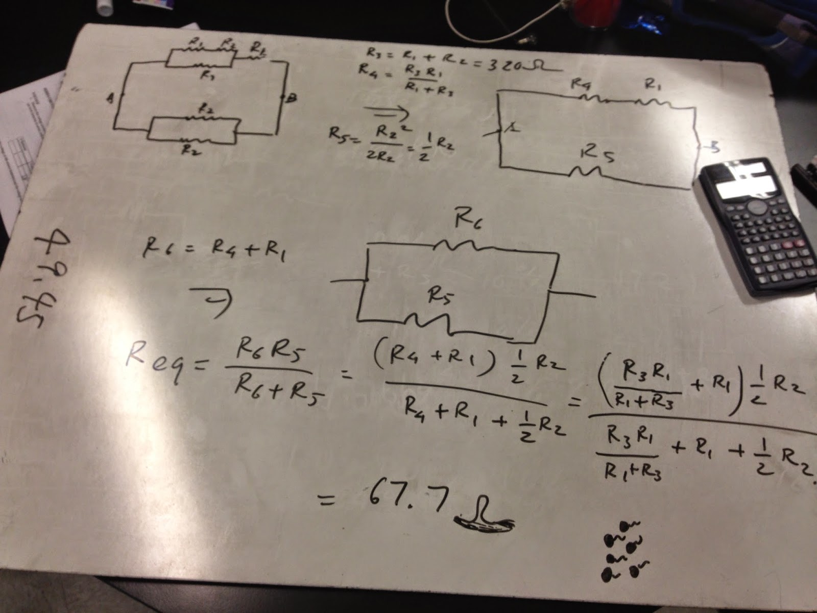
in series, total R=R1+R2+......
in parallel, total R=(R1*R2*....)/(R1+R2+....)
Conclusion:
Today in class, we learn
DC circuits and tested them in various layouts using a multimeter and how the current travels through the
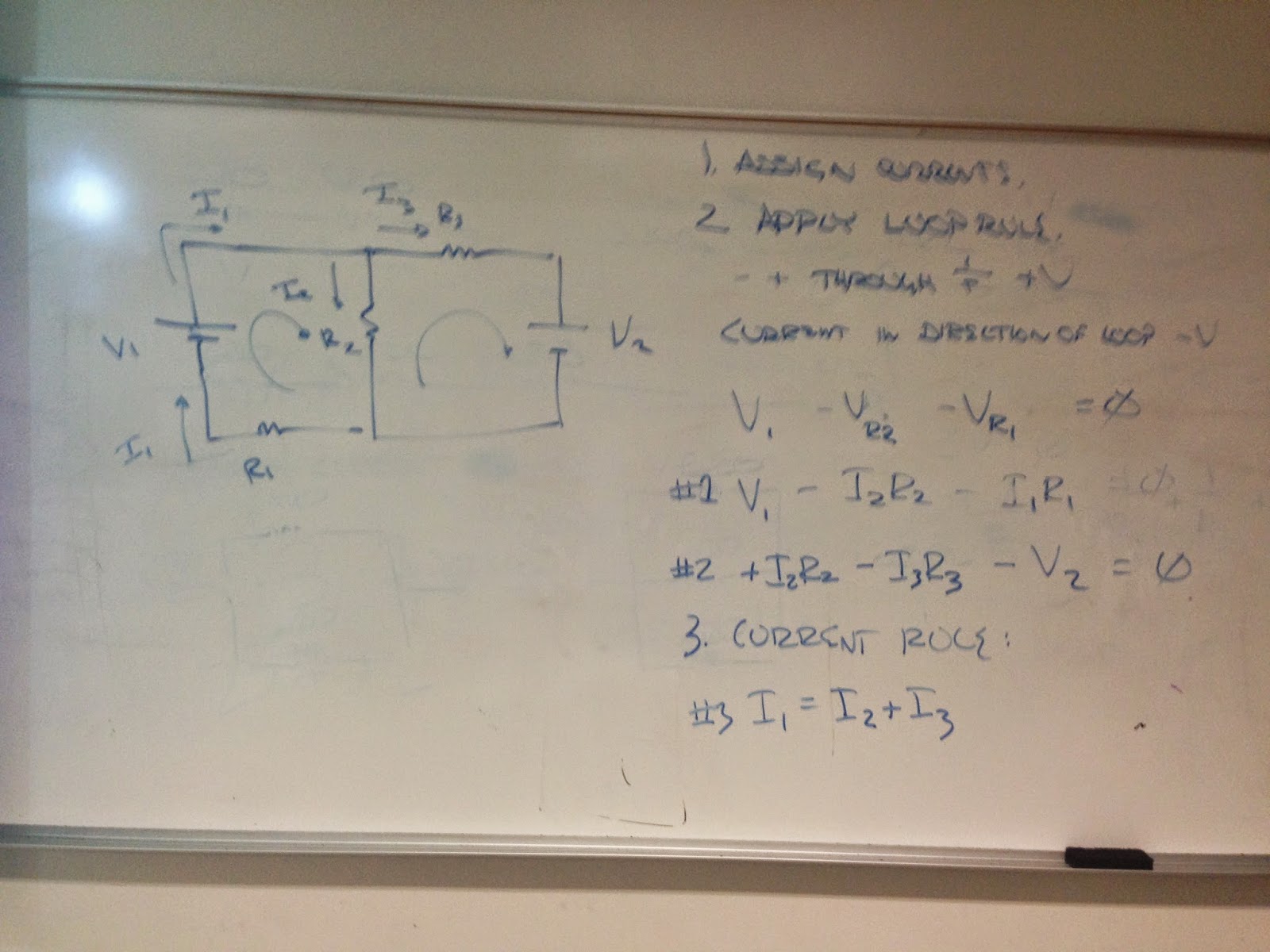
circuit. We used two equations which were Kirchhoff Rule and the Loop Rule.
We also anaylzed Voltage Law, and learned how to read resistors color code. So, at the end of the class, we are able to
solve circuits such as calculating the amount of current flowing through a
circuit, and the total resistance that a circuit when they were in parallel and series.
No comments:
Post a Comment