Thursday, April 30, 2015

4/30 Week 10 day 2 Charge Buildup and Decay in Capacitors

in today's class, We learn about RC Circuits.
At the beginning of the class, we did the Charge Buildup and Decay in Capacitors in this photo
we use two bulbs , 2 capacitors, 6 wires . to answer the questions.
in this photo, we first make a circle of a battery, a capacitor and a swith in series. When we close the swith, the bulb gets dimer and dimer and finnally it is not bright., the graph is on the photo.
Then we take away the battery and make the circle of just battery and capacitor in series,. and we saw that the bulb lights again, then it gets dimer.
In this photo, we draw a sketch of the brightness of the bulb and the time when it is placed across a charged capacitor without the battery present. 
It is a non-line graph. at first, the time is 0, the bulb is most brightness, then as time increases, the bulb gets dimer and dimer.
in this photo, we first use different batteries to charge two capacitance and then make them like the graph in the fist photo, and measure their voltage. 
In the second photo, on the left, it is our prediction. we think when we make the two capacitance together, the voltage should become 1V. But when we measure them, the voltage is just the average of them.
In this photo, we begin to make the experiment about Quantitative Measurements on An RC System.
We use a battery, a capacitor, a resistor, a voltage measuring lead, the computer, 6wires.
This is what we make like the graph on the lab manual. 
in this photo, we use logger pro to measure the two process, one is charge the capacitor, another is discharge the capacitor. The red one is charge, blue one is discharge.
In this photo, we use the equation V=IR, Q=CV to find the unit of RC, and we know the unit of I is c/s, and find the unit of RC is s(seconds).
in this photo, we use the equation V=Q/C,V=IR and I=dq/dt,to find dq/dt=-q/RC, and then we intergo both sides and find q=e^(-t/RC)

In this photo, professor made an experiment to show us, when turn on the green box, the two wires together will explode.
In this photo, if we only know the two graphs on the left, what can we get the graph of I vs t?
Because the voltage is increased by the time, and Brightness decreases by the time, we know Brightness decreases means the power is decreased, so according to equation P=IV, P decreases, V increases, we get that I should decrease.
Then we did a RC circuit problem in the photo
We use the two equations on this photo, one is charge, another is discharge.
First, we should find the RC in the photo, and we get that RC is 1s, another loop's RC is 0.
Then we just use Q=CV to find the Q, and we know the voltage of resistance is 1.5V, we use the equation of charge to find the t is 1.1s.
Then in this photo, when we turn off the switch, we will find that RC=3.5s, and we use the equation of discharge to find the time is 149s.
Conclusion:
In today’s class, we analyze the idea of capacitors and the charge buildup and discharging of capacitors in a circuit. We did many experiments on capacitors to understand how they work, and how they affect a circuit. We know that what happens when connected in series or parallel, and we did experiments at the different types of RC circuits about developing a relationship between their charging and discharging.  At the end of the class we did some excises to calculate capacitance, time constants, and maximum charge of a circuit 

Tuesday, April 28, 2015

4/28 week 10 day 1 Capacitors and Capacitance

Quiz:
at the beginning of the class, we did a quiz about the Kirchhoff's law.
We use Kirhhoff's Current Law and Kirchhoff Voltage Laws to find 3 equations to find the voltage, current and power of each line, and find the total power of them.
in this photo ,we begin to learn Capacitance. it can store charges, the unit is F, the symbol is C.
in this photo, Q is charges and V is voltage, and we know the equation Q=VC, and we can find the work done by capacitanor is W= 1/2*V^2*C.
in this photo, we measure the capacitance of different thickness of book, and we make a graph and find that C=k/d (d is thickness and K is constant.)
in this photo, we find the 3 things to influence the number of capacitance, they are area, thickness, and permittivity  the equation of C=kEA/d.
in this photo, we use the equation we find and calculate the area of the capacitor.
in this photo, the professor gives us two capacitors and we make them series and parallel, and measure their capacitance and we find the two equations in the photo.
Then we use the equations we find to find the total capacitance in this graph is 6.5 uF
in this photo, we redraw the graph and find the totoal capacitance is 52nF
Then we use the equation Q=CV to find the charge in every capacitrance
then we calculate the Voltage of C3 and find its charge is 7.32*10^-7C
Then in this photo, we find the total work by battery if all capacitors are charged, the equation is 1/2*C*V^2
Conlcusion:
Today in class, first, we did a quiz and reviewed the basics of how to calculate current and power in a circuit using Kirchhoff's Laws. We also learned about capacitance and how it functions in a circuit, by seeing how changing different variables affects capacitance, and how to compute total capacitance of circuits. When there are capacitances in series, the total C=1/C1+1/C2+…..; When there are capacitances in parallel, the total C=C1+C2+…… At the end of the class, we did an experiment about a culmination of capacitance, as well as recalling various rules about potential difference through a circuit.

Tuesday, April 21, 2015

4/21 week 9 day 1 DC circuits

at the beginning of the class, the professor shows us the exercise in the photo, there are 2 batteries, one swith and three bulbs, the question is what will happen if the switch is turned on.
in this photo, we answer the question and we think if the switch is turend on,  the No.1 bulb and No.2 bulb will stay the same, and the No.3 bulb stay off. 
Then the professor shows the equipment to us and what we predict is correct. 
Explain:
if the two batteries have voltage of 3,  and I note the voltage of different bulbs in the second photo. Because after the  switch is turend on,the voltage of No1 and No2 are same as the  switch is turend off, so these two bulbs stay the same. And the two sides of voltage in the No3 is 0, so the No3 bulb is not bright.
 in this photo, there is another exercise. and we should predict what will happen if the switch is turend on. 
and we predict that the two bulbs stay the same.
in this photo, the experience is like what we predict.
Explain:
When the switch is turend on, it it like one battery is parallel on the No1 bulb, so the voltage of the two side of No1 bulb doesn't change, and the parallel battery doesn't influence the No2 bulb. So the two bulbs stay the same.
in this photo, we have 5 situations that when we choose series or parallel of the bulbs, what the bulb and current will change. and we find that if we want the bulbs dimmer, we should make the bulbs series; if we want to make the bulbs brighter,we should parallel the bulbs

in this photo, we measure the different voltage or current in 4 situations.
First one:
we make the two resistants in series, and we use the same batteries, first time we use one battery, second time we use the two batteries in series, and mearsure the voltage of source and R1 and R2. And we find that in two times measures, the voltage of source= Vr1+Vr2
Second one:
the same experiment as first one ,but this time,we measure the voltage of source and the current of source Ir1and the current of Ir2 and Ir3, and we find  no matter how many batteries we use that all current in this circuit are same,Ir1=Ir2=Ir3.
Third one:
we make the two resistants in parallel, and we measure the voltage of source and the Vr1 and Vr2 of two resistants, and we find that no matter how many batteries we use, Voltage of source=Vr1=Vr2
Last one:
same as the third one ,but measure current of the source I1and the two resistantsIr1,Ir2, we find that the I1=Ir1+Ir2
 in this photo, we learn what the R of resistants is. there are usually 4 kinds of colors in one resistant, and the first three are certain and we can measure the R of resistant, but it is not certain, because the last kind of color is the uncertainty of R.
in this photo, we predict the 4 different resistants and their uncertainty. and we find the first resistant is bad.
in this photo the resistants are same, all of them are 620 om, and we calculate the different total R of 4 graphs
im this photo, we calculate the total R of this circle, and we uses the different laws of series and parallel to calculate. 
Explain:
in series, total R=R1+R2+......
in parallel, total R=(R1*R2*....)/(R1+R2+....)
this is the last excerise, there are three equations for V, I. we use Kirchhoff's Laws' two laws to find the solution.

Conclusion:
Today in class, we learn DC circuits and tested them in various layouts using a multimeter and how the current travels through the circuit. We used two equations which were Kirchhoff Rule and the Loop Rule.  We also anaylzed Voltage Law, and learned how to read resistors color code. So, at the end of the class, we are able to solve circuits such as calculating the amount of current flowing through a circuit, and the total resistance that a circuit when they were in parallel and series.


VPython#2

code:
we use the equationV=kQ/L*ln(r/ro) to find the potential electric energy of particals.


Thursday, April 16, 2015

4/16 week 8 day 2 Potential-of-Continuous-Charge-Distributions

The first thing we do today is that find the electric potential energy. In the photo, there is a ring with charge, and we should find one point's electric potential energy of the charge in the top of the ring. And we use the equation V=kq/r, and r =sqar(x^2+a^2)
in this photo, we find another  point's potential energy of different charge in the ring. one is in the top and another is at the middle of ring's one side. and we ues the same equation  V=kq/r, but the r is different, one is sqar(x^2+4a^2),another is sqar(2a^2+x^2)
in this photo, we find  the angle's relationship with a and x, and find three equations of theta.
in this photo, we change V=kq/r to V(theta)=kqcos(theta)/x
in this photo, we use the excle to find the total potential energy of the ring, the ring divided into 16 parts, and one part's potential energy is V=kq/r, the total potential energy is that add all parts together.
in this photo, we calculate the total electric potential energy  of the ring and find it is same in the excle we did.

in this photo, we use the potential energy V to find the electric field E, we put the equation cos(theta)=x/sqar(x^2+a^2) and r=sqar(a^2+x^2) to E=kQcos(theta)/r^2, and we find that E=kQx/(x^2+a^2)^(3/2).
in this photo, we use the antiderivative to find the change of the potential energy V, we use the equation E=kQx/(x^2+a^2)^(3/2), and find out that V=kQ/sqar(x^2+a^2) from infinite to x.

in this photo, we should calculate the potential electric energy of a special point.
in this photo, we use the equation at the bottom of the graph to find the potential electric energy.
in this photo, we use the excle to find the answer and find it is same as what we did in the last photo.
in this photo, there is a particl has positive charge, and we draw the points which have the same potential electric energy and line them, we fing these particals can make different circle.
in this photo, we have two different lines, one has positive charge, another has negative charge. and we draw  the surface that has same potential electric energy.
in this photo, we have a couple of dipole that draw the surface that has same potential electric energy.
 
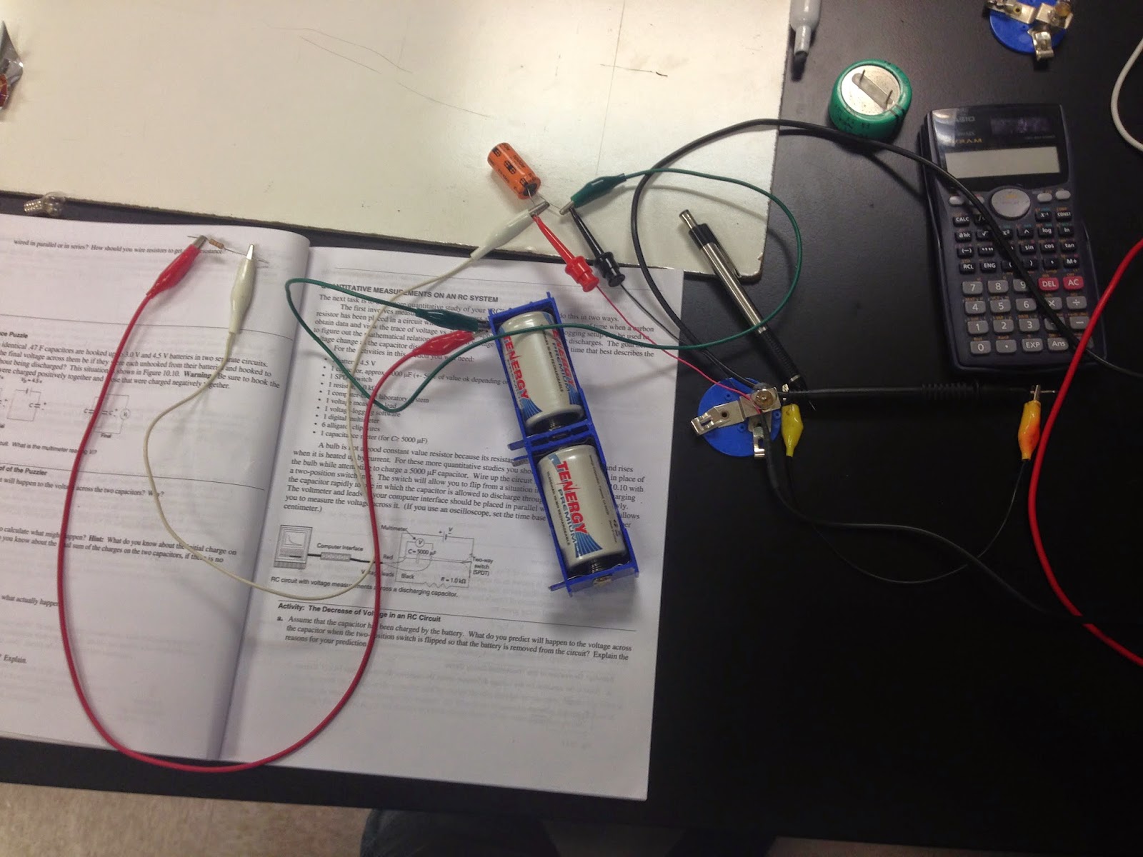
Pictured above are the various pieces of equipment used to run this activity. We had a power source connected to two points on the conductive paper, which we then turned on to run a voltage through. We then used a voltmeter to measure the magnitude of the voltage at various distances. This was done by placing both of the voltmeter needles are precise lengths from each other. The Position values shown below depict the distance and direction that one of the needles moved in relation to the other stationary needle, which was left at the origin (one of the metal circles on the paper). 

then we start to do another experiment in the photo.we use cork board, conductive paper,power supple,voltmeter to find at the different distant, what is the voltage between the two metallic paint marks on the paper.


in this photo, we use the excle to find the at the different position what is the voltage and the change of V/x

Conlcusion:
Today in class, we build three different methods of finding potential difference V between two points. And we calculate the potential from a charged ring using the limit of the sum as an integral and also using the integral of the Electric field as both gives the same results by using a spreadsheet, algebraically/trigonometrically by solving for V, and solving for V using Gauss' Law. The idea of equipotential surface is important for analyzing potentials on a surface as the potentials are the same at every point on the surface in which it is perpendicular to the electric field. It allowed us to gather some data and calculate how much work a charge would have to do to move from one point on the paper to another using the equation W=QdV.