Thursday, May 14, 2015

5/14 week12 day 2 Lenz's Law and Faraday's law

At the beginning of the class, the professor gives us two lines, both of which have same current, and then we draw the magnetic field in both of them and find the magnetic force of each of them.
Then we know that B=u/4pi*Idl/a^2 so we get that F=u/2pia*I_0*I_1*L
Then the professor shows us the experiment. When closing the switch, and the two lines were charged, they get closer thant no charged.
Then we make a prediction, we think that because there are forces that makes them closer, but actually, beacuse of the power is alternating current, so there is no force.
Then in these two photos, the professor use logger pro to make a graph of the change of magnetic field as time changes. and we draw the north and south poles in the graph.Professor then performed the experiment by switching on the power supply causing an alternating current in the two parallel lines. There are in fact no net forces acting as there due to the alternating current. Then he uses logger pro to show magnetic field in respect to time.  Two cycles here are observed in which we can interpret the magnetic field oscillations caused by the north and south poles by applying Faraday's law
We use logger pro to collect data and make a graph in this photo,
in this photo, we caculate the flux of magnet. the first one, because the B and A are parallel, so the flux is 0, and the second one, because they are perpendicular so the flux=B*a*b
in this photo, we begin to do the experiment about the magnetic field in a loop.
we collect the data and fill the form.

in these two photo, the professor use a magnet to cross the loops and when it enter or leave the loops, the dash board will change. Professor uses a bar magnet and galvanometer and allowed the magnet to go back and forth causing movement (changing magnetic fields) which stimulates a current seen in the movement of the meter through induction. As he stops in the center of the coil there is no change in the meterwhen it stay in the loops, it doesn't change 
in this photo, we list 4 reasons that can influence the dash board.If we want to maximize the current on an induced EMF we can add more loops on the coil, have a bigger loop by increasing the area, use a bigger magnet, and also move the magnet faster
Then we use this equipment in the photo to see what will happen


in this video, when we put a loop of coppr or alaluminium on the equipment , it can suspend。

But when the loop is cut, it doesnot suspend any more
Then in this photo, we draw the graph of force, magnetic field. When the north pole of the magnet is going toward a loop, the flux increases and an upward secondary magnetic field is created causing a counterclockwise current. The changing flux created by the magnetic field created by the induced emf causes the the loop to float due to the force upward.

in this photo, we put the magnet into the magnetic tube and it will drop slower than the not magnetic tube,


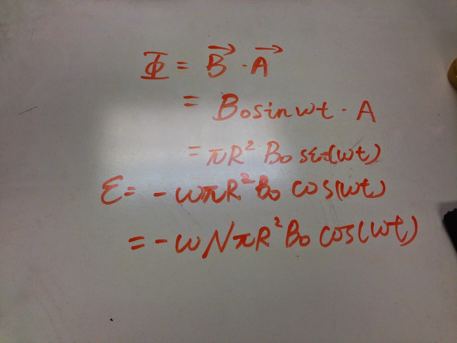
in these two photos, we first find the E that created by the moving of magnet and draw the two graphs of B and E
Conclusion:
In today’s class, we learned Lenz's Law and Faraday's Law to see how we could induce a current using magnetic fields and magnetic fields, forces, torque, and flux. find that an EMF and flux explains the relationship between the two by using Lenz's law and Faraday's Law to magnetic fields. We did many experiments that made a steel ring and we saw that the forces of the magnetic field create some objects to levitate just like the rings.

Tuesday, May 12, 2015

5/12 week 12 day 1 Magnetism ,Electricity and motor

at the beginning of the class, the professor let us draw two graphs about the bin before and after magnetizing.
The first one is the bin before magnetizing, the particles in the bin are chaotic, so the net force can be canceled.
The second one is the bin after magnetizing. Through magnetizing, the particles in bin are all well-organized, so it can show the north and south poles.
in this photo, we think about two ways to destory a magnet. one is heating and another is hitting it.

Then in these two photos, the professor heats the bin and show us the result, and we find that after heating the bin, it doesn't have magnetism and it can't change the direction of compass.
In this photo, we begin to do another exercise, make the loop galvanical and give it a magnet field, the direction is upward. Then we find that only the top and bottom lines has Force and the net force is 0.
Then we use the equation torque=F*r ,and F=BIL to find the torque=1/2BIL^2, and the net torque is BIL
In this photo, we use the three equation in yellow to answer the question of the example at the bottom.
in this photo, we use the equation torque=NIABsin(theta) to find the torque , we need to be careful that the theta should be 60, not 30.
Then the professor change the rectangle to circle. the equation is same:torque=NIAB=1885N*m
in this photo, the professor  shows us motor in parts.
There are three ways to break a motor, the first one is brushes, the second one is commutator, and the last way is coil contract fails.
Then we start to do the experiment about electric motor, we use a battery, two fixed contacts and a split ring commutator to complete this experiment
in this photo, we draw four situations about the motion of electric motor, the top two have same direction of current, but the different direction of magnet field. The left two have same direction of magnet field, but direction of current.
We found that when we change the direction of current or the direction of magnet field, the direction of rotation would change.
 Then we answer the question on the lab manual.
Then we made a simple electric motor by ourselves. We use small gauge enamel coated wire, two large paper clips, block of wood ,magnet, power supply and two alligator clip connectors.

This is the video we made and shows the success of this small electric motor.
in this photo, we use the equation E=VB, E=V_h/W and I=roh*q*V*W*t to find the V_h=BI/roh*q*t
The professor makes a galvanical wire in the middle, before closing the switch of  the battery, we observe that all compass are direct to north
 In this photo, we predict after closing the switch of the battery, what will happen. and we guess that the north of  compass will direct in a circle.
  in this photo, the professor shows us the result of this experiment and our predict is correct.
In this photo, the professor changes the direction of current and we find that all compass's north direct an opposite direction., but still form a circle,
 In these two photos, the professor let us predict the direction of north pole of three compass and we draw the graph on the second photo.
in this photo, we find the equation of B

in this photo, we get the relationship between the Force of Magnet field and the force of electric field is about the velocity of light and the speed of particle.
Conclusion:

In today’s class, we learned a lot about magnetism and the properties that are inside the magnets and how they interact with the other.  We learned that torque is generated in a current loop in a magnetic field due to forces on the sides when there are N turns of wire. We learned about another right hand rule which shows us the direction of the magnetic field.  We learned how to create a magnet and how to destroy a magnet. We were also introduced to motors and use magnetic fields to rotate the motor. We also created a motor with a wires, paper clips, and a battery.

Friday, May 8, 2015

5/8 week 11 day 2 Magnetic Fields and Magnetic Forces

At the beginning of the class, the professor gives us a bar magnet and a samll compass. Then we put the compass around the magnet and observe the change of the compass and draw the picture in the photo.
we find that all arrows are leave from north pole and direct to south pole.
in this photo, we make all arrows together and draw a graph. 
in this photo, the professor put iron filings sprinkled around the magnet and we observe that there are circles from north pole to south pole
in this photo, we draw three circles, one includes one of poles, another includes both of poles and the last one does not include any pole. and we should find how many arrows in and out the circles. and What we find is at the bottom of the photo. 
Then the professor shows us a large magnet and put a iron wire on it. and when we take the wire to close to a compass and we find that the arrow in compass changes its position. it says that the wire has magnetism。
Then the professor cut the iron wire to two small wires, and put one of the small wire's one side near the compass , the arrow in compass changes its position as well, and then put another side and the arrow in compass changes its position to oppisite direction. it is said that the iron wire also has two poles./

in this photo, we use the equation to find the magnetic flux
in this photo, when we make the area and magnetic induction line parallel, we know that the  magnetic flux is 0
in this photo,the professor gives us a oscillooscope and put a magnet near it, and we find that when magnet in different position and move, the bright point will go different direction,.
in this photo, we figure out two vectors of points and how the point move.


In this photo, professor gives us an equation to find the unit of B . and we know that the unit of F is N, q is C, v is m/s and we get that the unit of B, T=N/A*m
in this photo, we did an exericse about the force of charge in magnetic field.
in this photo, we use the equation F=qvB to find the F is 6.25*10^-16 and the acceleration a= 3.74*10^11m/s
in this photo, professor let us to prdict the motion of the charge when put it into magnetic field. and we find the motion is circle motion and we know that F=qvB=mv^2/r and we find the radius r=mv/qB
in these two photos, we use the equation r=mv/qB and v=2pirf to find the B is 0.0875T

 Then in these two photos, the professor put a wire line in the magnet and make the connect the line to battery. and we find when the wire connect to the battery, the wire will change its position, up or down.
then we do the questions in this photo.
For a, t=L/v 
For b, I=q/t
For c, we got that F=qvB=ILB
For d,  it is in the second photo, dF=IdLB
in this photo, we begin to do experiment about the loop.
in this photo, the direction of magnetic filed is from left to right, and the direction of current is clockwise,we draw the Fand its direction and we find that the top and bottom has no force and the direction of F of left is inside the table and the right is outside the table.so  the loop will rotate /
in this photo, we change the direction of magnetic filed to from outside to inside, and the current is also clockwise and we find that the force of 4 sides are same but the directions are to 4 different direction, so the loop will not move.
Then the professor let us make a prediction about how the loop will move and we think it will spin up 90,because we did the two different solutions before.
Conclusion:
Today, in class, we learned about magnetism and its properties. We saw how the magnetic fields looks like on the magnet.  Then we learned about the right hand rule when it comes to currents and force. We also saw that current, length and magnetic field determine the force of the magnetic field. When it is given magnetic charge by being placed in a horseshoe magnet and cut into half, the magnetic charge is shown by using a compass.